简体中文
 English
 اللغة العربية
 Español



Coil Set (Longitudinal Bow): The sheet curves upward or downward along the rolling direction like a banana, driven by the metal’s cylindrical coiling memory.
Crossbow (Transverse Camber): The sheet arches across its width, typically caused by uneven cooling across the strip edges during rolling or slitting.
Edge Wave & Center Buckle: Ripples along the outer edges or a raised dome in the center of the sheet. This occurs when the edges and center of the strip elongate at different rates during rolling, creating the hardest type of latent stress to remove.
The Industry Reality: Basic entry-level CTL lines merely "press" the sheet flat using heavy rollers. While the sheet looks geometrically flat on an inspection table, its internal stress field remains tightly wound like a spring. The moment a laser beam or punch press releases that tension along a cut path, the sheet immediately distorts.
| Leveling Technology | Core Mechanical Principle | Stress-Relief Capability | Ideal Materials & Applications | Laser Cutting Performance |
|---|---|---|---|---|
| Standard Multi-Roll Leveling | Passes strip through staggered upper and lower work rolls to induce alternating bending cycles. | Moderate (Removes coil set and crossbow, but struggles with edge wave/center buckle) | General structural parts, enclosures, non-critical shearing | High risk of warping when cutting intricate profiles or dense perforations |
| Precision Multi-Roll Leveling | Uses small-diameter, closely spaced work rolls supported by adjustable hydraulic back-up rolls. | High (Targets localized edge/center waves; achieves flatness ≤ 1.0 mm/m) | High-end sheet metal, elevator panels, precision medium-plate laser cutting | Stable, reliable performance for most commercial laser applications |
| Stretcher / Tension Leveling | Combines bending rolls with a longitudinal pure tensile pull exceeding the material's yield strength. | Ultimate (Completely resets the internal stress field for true "zero-stress" flatness) | Aerospace, precision electronics, Advanced High-Strength Steels (AHSS), thin mirror sheets | Flawless performance; zero thermal bowing even during heavy skeleton cutting |
Stop-Start Shearing: The line feeds the strip to the target length, comes to a complete halt, and drops the guillotine blade. Advantage: Exceptional length accuracy (typically within ±0.2 mm). Drawback: Every momentary stop leaves subtle transverse "roll marks" where the work rolls rest against the strip—making it unsuitable for 8K Mirror or high-gloss architectural stainless steel.
Flying Shear (Rotary / Moving Shear): The shear carriage accelerates to match the exact speed of the moving strip, cutting on the fly without stopping the line. Advantage: High throughput and zero surface roll marks or chatter, making it mandatory for exposed automotive panels and luxury architectural sheets.
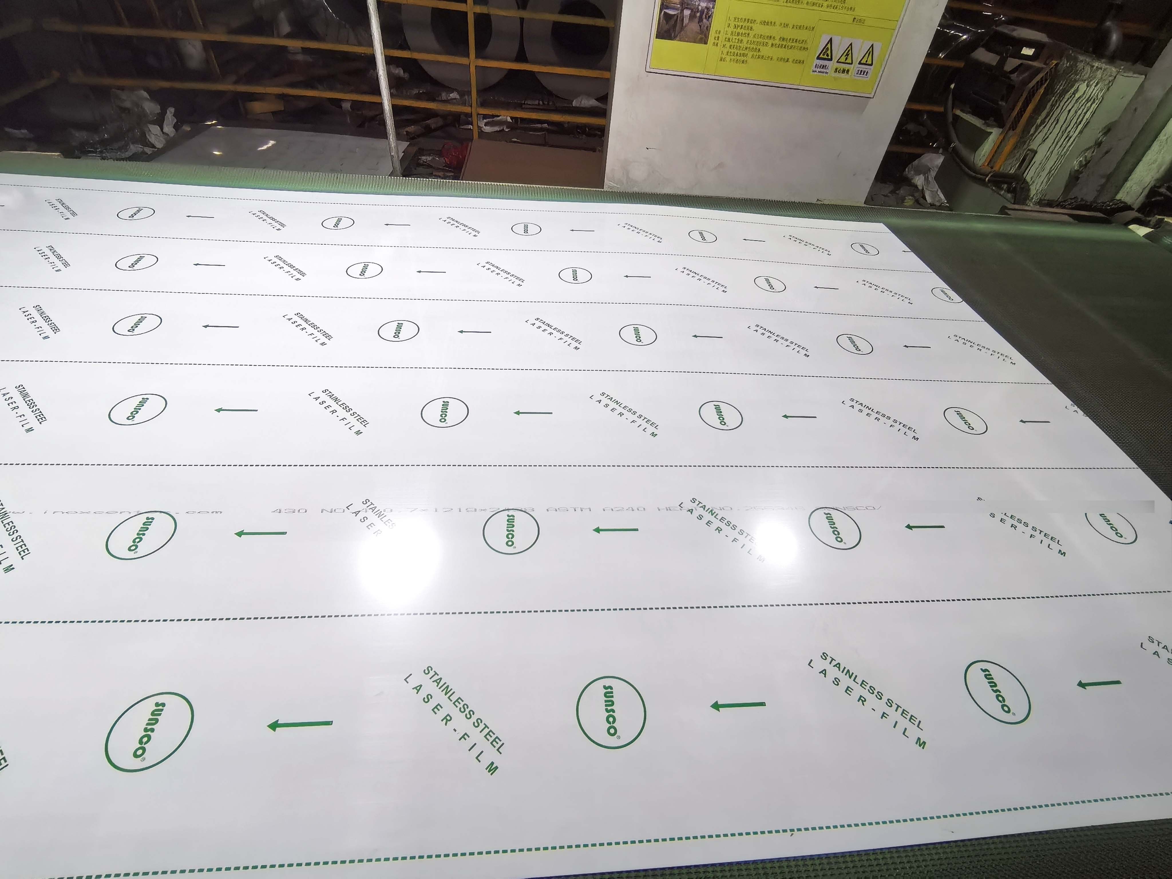
1. Specify Quantitative Flatness Standards: Never write simply "must be flat" on a Purchase Order. For laser-grade sheets, mandate flatness deviation ≤ 1.0 mm/m (or specify ASTM A480 / EN 10029 Special/Precision Flatness tolerances), and explicitly require Tension-Leveled material for thin-gauge high-precision jobs.
2. The Surface Plate & Feeler Gauge Test: Place a sample sheet naturally onto a certified cast-iron inspection table without applying downward hand pressure. Use a feeler gauge to measure the maximum gap between the sheet edge (or center) and the table surface. Any unrestrained lift exceeding 1.5mm indicates residual longitudinal or transverse stress.
3. Diagonal Squareness Verification: Measure both corner-to-corner diagonals on sampled sheets. A well-calibrated precision CTL line with servo-driven side guides will hold diagonal variance within ≤ 1.0 mm, ensuring accurate datum alignment for CNC press brakes and robotic welding cells.
-
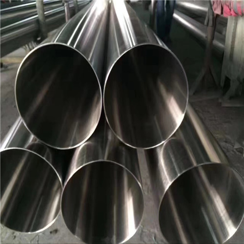
[Company news] High quality supply of stainless steel pipe for ho......
2022-04-10
After years of development and innovation, the stainless steel pipe for household decoration has evolved from a single "slot body" to a "system" produ......
-

[Company news] Warmly celebrate the official launch of the fsunsc......
2005-07-19
Foshan Sunsco Technology Co.Ltd is located in Foshan City of China, focusing on stainless steel area for more than 12 years. With the support of the m......
-
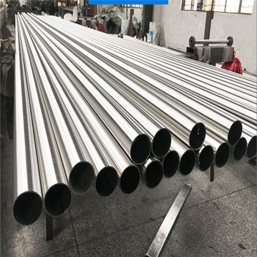
[Industry dynamics] 304 stainless steel pipe market improves
2021-12-20
FSUNSCO Company operates a series of 304 stainless steel tubes all the year round. Stainless steel pipe, 304 stainless steel plate, 304 stainless stee......
-
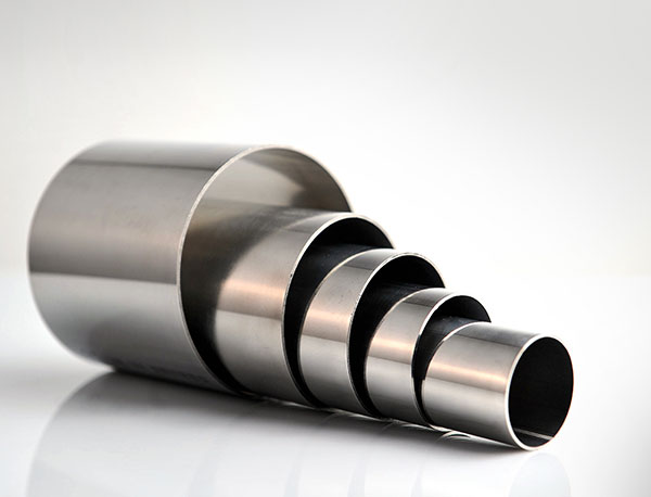
[Industry dynamics] What can help us to quickly distinguish between 30......
2020-06-20
Many friends will worry when choosing stainless steel, this is because he can not distinguish between 304 and 201 stainless steel, how to quickly dist......